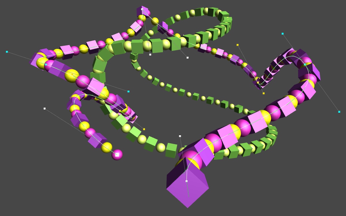
This tutorial will take you from creating a simple line all the way to editing your own Beziér splines. You’ll learn to
- Create a custom editor;
- Draw in the scene view;
- Support editing via the scene view;
- Create Beziér curves and understand the math behind them;
- Draw curves and their direction of movement.
- Build Beziér splines by combining curves;
- Support free, aligned, and mirrored control points;
- Support looping splines;
- Move and place objects along a spline.
This tutorial builds on the foundation laid by previous tutorials. If you completed the Maze tutorial then you’re good to go.
This tutorial was made with Unity 4.5.2. It might not work for older versions.
Lines
Let’s start simple by creating a line component. It needs two points – p0 and p1 – which define a line segment that goes from the first to the second.
using UnityEngine;

public class Line : MonoBehaviour {

	public Vector3 p0, p1;
}
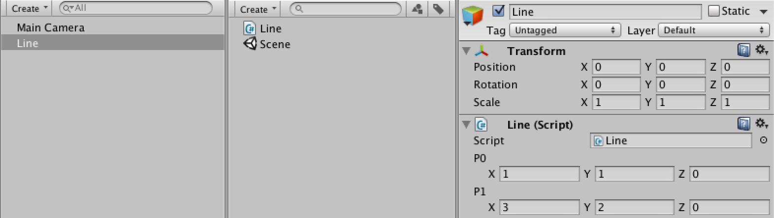
While we can now create game objects with line components and adjust the points, we don’t see anything in the scene. Let’s provide some useful visual information when our line is selected. We can do this by creating a custom inspector for our component.
Editor-related code needs to be placed inside an Editor folder, so create one and put a new LineInspector script in it.
The inspector needs to extend UnityEditor.Editor. We also have to give it the UnityEditor.CustomEditor attribute. This lets Unity know that it should use our class instead of the default editor for Line components.
using UnityEditor;
using UnityEngine;

[CustomEditor(typeof(Line))]
public class LineInspector : Editor {
}
An empty editor does not change anything. We need to add an OnSceneGUI method, which is a special Unity event method. We can use it to draw stuff in the scene view for our component.
The Editor class has a target variable, which is set to the object to be drawn when OnSceneGUI is called. We can cast this variable to a line and then use the Handles utility class to draw a line between our points.
	private void OnSceneGUI () {
		Line line = target as Line;

		Handles.color = Color.white;
		Handles.DrawLine(line.p0, line.p1);
	}
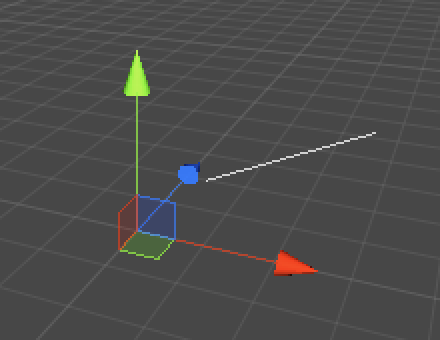
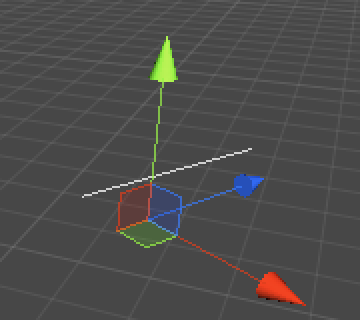
We now see the line, but it doesn’t take its transform’s settings into account. Moving, rotating, and scaling does not affect them at all. This is because Handles operates in world space while the points are in the local space of the line. We have to explicitly convert the points into world space points.
	private void OnSceneGUI () {
		Line line = target as Line;
		Transform handleTransform = line.transform;
		Vector3 p0 = handleTransform.TransformPoint(line.p0);
		Vector3 p1 = handleTransform.TransformPoint(line.p1);

		Handles.color = Color.white;
		Handles.DrawLine(p0, p1);
	}
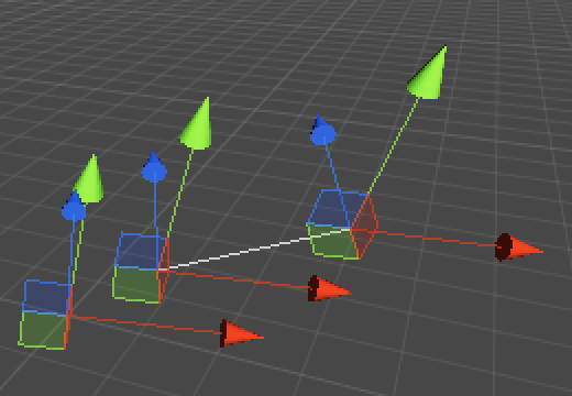
Besides showing the line, we can also show position handles for our two points. To do this, we also need our transform’s rotation so we can align them correctly.
	private void OnSceneGUI () {
		Line line = target as Line;
		Transform handleTransform = line.transform;
		Quaternion handleRotation = handleTransform.rotation;
		Vector3 p0 = handleTransform.TransformPoint(line.p0);
		Vector3 p1 = handleTransform.TransformPoint(line.p1);

		Handles.color = Color.white;
		Handles.DrawLine(p0, p1);
		Handles.DoPositionHandle(p0, handleRotation);
		Handles.DoPositionHandle(p1, handleRotation);
	}
Although we now get handles, they do not honor Unity’s pivot rotation mode. Fortunately, we can use Tools.pivotRotation to determine the current mode and set our rotation accordingly.
		Quaternion handleRotation = Tools.pivotRotation == PivotRotation.Local ?
			handleTransform.rotation : Quaternion.identity;
To make the handles actually work, we need to assign their results back to the line. However, as the handle values are in world space we need to convert them back into the line’s local space with the InverseTransformPoint method. Also, we only need to do this when a point has changed. We can use EditorGUI.BeginChangeCheck and EditorGUI.EndChangeCheck for this. The second method tells us whether a change happened after calling the first method.
		EditorGUI.BeginChangeCheck();
		p0 = Handles.DoPositionHandle(p0, handleRotation);
		if (EditorGUI.EndChangeCheck()) {
			line.p0 = handleTransform.InverseTransformPoint(p0);
		}
		EditorGUI.BeginChangeCheck();
		p1 = Handles.DoPositionHandle(p1, handleRotation);
		if (EditorGUI.EndChangeCheck()) {
			line.p1 = handleTransform.InverseTransformPoint(p1);
		}
Now we can drag our points in the scene view!
There are two additional issues that need attention. First, we cannot undo the drag operations. This is fixed by adding a call to Undo.RecordObject before we make any changes. Second, Unity does not know that a change was made, so for example won’t ask the user to save when quitting. This is remedied with a call to EditorUtility.SetDirty.
		EditorGUI.BeginChangeCheck();
		p0 = Handles.DoPositionHandle(p0, handleRotation);
		if (EditorGUI.EndChangeCheck()) {
			Undo.RecordObject(line, "Move Point");
			EditorUtility.SetDirty(line);
			line.p0 = handleTransform.InverseTransformPoint(p0);
		}
		EditorGUI.BeginChangeCheck();
		p1 = Handles.DoPositionHandle(p1, handleRotation);
		if (EditorGUI.EndChangeCheck()) {
			Undo.RecordObject(line, "Move Point");
			EditorUtility.SetDirty(line);
			line.p1 = handleTransform.InverseTransformPoint(p1);
		}
Curves
It is time to upgrade to curves. A curve is like a line, but it doesn’t need to be straight. Specifically, we’ll create a Beziér curve.
A Beziér curve is defined by a sequence of points. It starts at the first point and ends at the last point, but does not need to go through the intermediate points. Instead, those points pull the curve away from being a straight line.
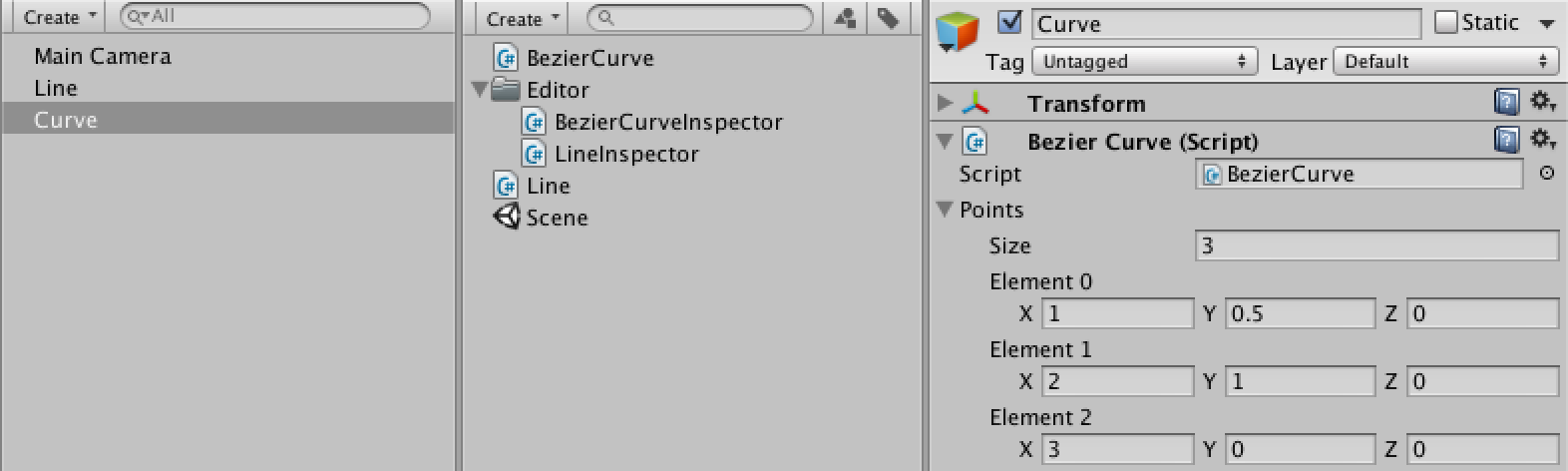
Create a new BezierCurve component and give it an array of points. Also give it a Reset method that initializes it with three points. This method also functions as a special Unity method, which is called by the editor when the component is created or reset.
using UnityEngine;

public class BezierCurve : MonoBehaviour {

	public Vector3[] points;

	public void Reset () {
		points = new Vector3[] {
			new Vector3(1f, 0f, 0f),
			new Vector3(2f, 0f, 0f),
			new Vector3(3f, 0f, 0f)
		};
	}
}
We also create an inspector for the curve, based on LineInspector. To reduce code repetition, we move the code that shows a point to a separate ShowPoint method that we can call with an index. We also turn curve, handleTransform, and handleRotation into class variables so we don’t need to pass then to ShowPoint.
While it is a new script, I’ve marked the differences as if we modified LineInspector.
using UnityEditor;
using UnityEngine;

[CustomEditor(typeof(BezierCurve))]
public class BezierCurveInspector : Editor {

	private BezierCurve curve;
	private Transform handleTransform;
	private Quaternion handleRotation;

	private void OnSceneGUI () {
		curve = target as BezierCurve;
		handleTransform = curve.transform;
		handleRotation = Tools.pivotRotation == PivotRotation.Local ?
			handleTransform.rotation : Quaternion.identity;

		Vector3 p0 = ShowPoint(0);
		Vector3 p1 = ShowPoint(1);
		Vector3 p2 = ShowPoint(2);

		Handles.color = Color.white;
		Handles.DrawLine(p0, p1);
		Handles.DrawLine(p1, p2);
	}

	private Vector3 ShowPoint (int index) {
		Vector3 point = handleTransform.TransformPoint(curve.points[index]);
		EditorGUI.BeginChangeCheck();
		point = Handles.DoPositionHandle(point, handleRotation);
		if (EditorGUI.EndChangeCheck()) {
			Undo.RecordObject(curve, "Move Point");
			EditorUtility.SetDirty(curve);
			curve.points[index] = handleTransform.InverseTransformPoint(point);
		}
		return point;
	}
}
The idea of Beziér curves is that they are parametric. If you give it a value – typically named t – between zero and one, you get a point on the curve. As t increases from zero to one, you move from the first point of the curve to the last point.
To show our curve in the scene, we can approximate it by drawing straight lines between successive steps on the curve. We can do this with a simple loop, assuming our curve has a GetPoint method. We also keep drawing the straight lines between the points, but change their color to gray.
	private const int lineSteps = 10;

	private void OnSceneGUI () {
		curve = target as BezierCurve;
		handleTransform = curve.transform;
		handleRotation = Tools.pivotRotation == PivotRotation.Local ?
			handleTransform.rotation : Quaternion.identity;

		Vector3 p0 = ShowPoint(0);
		Vector3 p1 = ShowPoint(1);
		Vector3 p2 = ShowPoint(2);

		Handles.color = Color.gray;
		Handles.DrawLine(p0, p1);
		Handles.DrawLine(p1, p2);

		Handles.color = Color.white;
		Vector3 lineStart = curve.GetPoint(0f);
		for (int i = 1; i <= lineSteps; i++) {
			Vector3 lineEnd = curve.GetPoint(i / (float)lineSteps);
			Handles.DrawLine(lineStart, lineEnd);
			lineStart = lineEnd;
		}
	}
Now we have to add the GetPoint method to BezierCurve otherwise it won’t compile. Here we again make an assumption, this time that there’s a utility Beziér class that does the calculation for any sequence of points. We feed it our points and transform the result to world space.
	public Vector3 GetPoint (float t) {
		return transform.TransformPoint(Bezier.GetPoint(points[0], points[1], points[2], t));
	}
So we add a static Bezier class with the required method. For now, let’s ignore the middle point and simply linearly interpolate between the first and last point.
using UnityEngine;

public static class Bezier {

	public static Vector3 GetPoint (Vector3 p0, Vector3 p1, Vector3 p2, float t) {
		return Vector3.Lerp(p0, p2, t);
	}
}
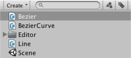
Of course, linear interpolation between the end points totally ignores the middle point. So how do we incorporate the middle point? The answer is to interpolate more than once. First, linearly interpolate between the first and middle point, and also between the middle and last point. That gives us two new points. Linearly interpolating between those two gives us the final point on the curve.
	public static Vector3 GetPoint (Vector3 p0, Vector3 p1, Vector3 p2, float t) {
		return Vector3.Lerp(Vector3.Lerp(p0, p1, t), Vector3.Lerp(p1, p2, t), t);
	}
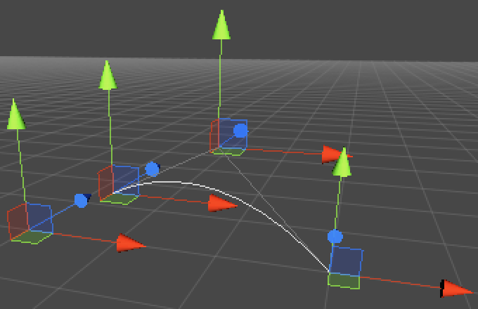
This kind of curve is known as a quadratic Beziér curve, because of the polynomial math involved.
The linear curve can be written as B(t) = (1 – t) P0 + t P1.
One step deeper you get B(t) = (1 – t) ((1 – t) P0 + t P1) + t ((1 – t) P1 + t P2). This is really just the linear curve with P0 and P1 replaced by two new linear curves. It can also be rewritten into the more compact form B(t) = (1 – t)2 P0 + 2 (1 – t) t P1 + t2 P2.
So we could use the quadratic formula instead of three calls to Vector3.Lerp.
	public static Vector3 GetPoint (Vector3 p0, Vector3 p1, Vector3 p2, float t) {
		t = Mathf.Clamp01(t);
		float oneMinusT = 1f - t;
		return
			oneMinusT * oneMinusT * p0 +
			2f * oneMinusT * t * p1 +
			t * t * p2;
	}
Now that we have a polynomial function, we can also describe its derivatives. The first derivative of our quadratic Beziér curve is B'(t) = 2 (1 – t) (P1 – P0) + 2 t (P2 – P1). Let’s add it.
	public static Vector3 GetFirstDerivative (Vector3 p0, Vector3 p1, Vector3 p2, float t) {
		return
			2f * (1f - t) * (p1 - p0) +
			2f * t * (p2 - p1);
	}
This function produces lines tangent to the curve, which can be interpreted as the speed with which we move along the curve. So now we can add a GetVelocity method to BezierCurve.
Because it produces a velocity vector and not a point, it should not be affected by the position of the curve, so we subtract that after transforming.
	public Vector3 GetVelocity (float t) {
		return transform.TransformPoint(Bezier.GetFirstDerivative(points[0], points[1], points[2], t)) -
			transform.position;
	}
Now we can visualize the speed along the curve in BezierCurveInspector‘s OnSceneGUI method.
		Vector3 lineStart = curve.GetPoint(0f);
		Handles.color = Color.green;
		Handles.DrawLine(lineStart, lineStart + curve.GetVelocity(0f));
		for (int i = 1; i <= lineSteps; i++) {
			Vector3 lineEnd = curve.GetPoint(i / (float)lineSteps);
			Handles.color = Color.white;
			Handles.DrawLine(lineStart, lineEnd);
			Handles.color = Color.green;
			Handles.DrawLine(lineEnd, lineEnd + curve.GetVelocity(i / (float)lineSteps));
			lineStart = lineEnd;
		}
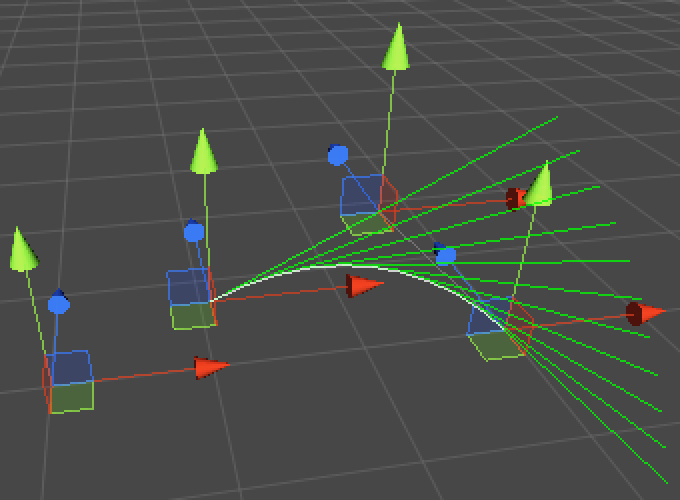
We can clearly see how the velocity changes along the curve, but those long lines are cluttering the view. Instead of showing the velocity, we can suffice with showing the direction of movement.
		Vector3 lineStart = curve.GetPoint(0f);
		Handles.color = Color.green;
		Handles.DrawLine(lineStart, lineStart + curve.GetDirection(0f));
		for (int i = 1; i <= lineSteps; i++) {
			Vector3 lineEnd = curve.GetPoint(i / (float)lineSteps);
			Handles.color = Color.white;
			Handles.DrawLine(lineStart, lineEnd);
			Handles.color = Color.green;
			Handles.DrawLine(lineEnd, lineEnd + curve.GetDirection(i / (float)lineSteps));
			lineStart = lineEnd;
		}
Which requires that we add GetDirection to BezierCurve, which simply normalizes the velocity.
	public Vector3 GetDirection (float t) {
		return GetVelocity(t).normalized;
	}
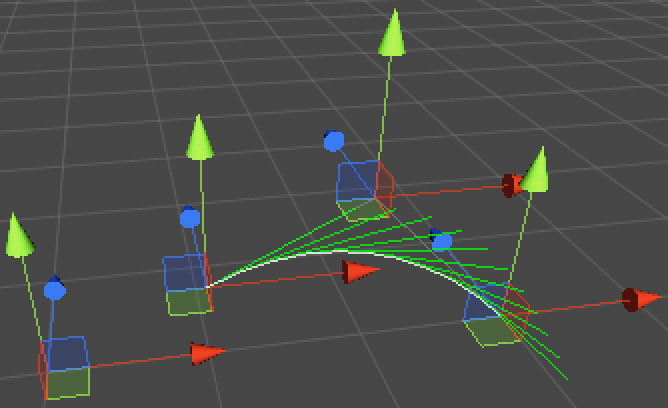
Let’s go a step further and add new methods to Bezier for cubic curves as well! It works just like the quadratic version, except that it needs a fourth point and its formula goes another step deeper, resulting in a combination of six linear interpolations. The consolidated function of that becomes B(t) = (1 – t)3 P0 + 3 (1 – t)2 t P1 + 3 (1 – t) t2 P2 + t3 P3 which has as its first derivative B'(t) = 3 (1 – t)2 (P1 – P0) + 6 (1 – t) t (P2 – P1) + 3 t2 (P3 – P2).
	public static Vector3 GetPoint (Vector3 p0, Vector3 p1, Vector3 p2, Vector3 p3, float t) {
		t = Mathf.Clamp01(t);
		float oneMinusT = 1f - t;
		return
			oneMinusT * oneMinusT * oneMinusT * p0 +
			3f * oneMinusT * oneMinusT * t * p1 +
			3f * oneMinusT * t * t * p2 +
			t * t * t * p3;
	}

	public static Vector3 GetFirstDerivative (Vector3 p0, Vector3 p1, Vector3 p2, Vector3 p3, float t) {
		t = Mathf.Clamp01(t);
		float oneMinusT = 1f - t;
		return
			3f * oneMinusT * oneMinusT * (p1 - p0) +
			6f * oneMinusT * t * (p2 - p1) +
			3f * t * t * (p3 - p2);
	}
With that, we can upgrade BezierCurve from quadratic to cubic by taking an additional point into consideration. Be sure to add the fourth point to its array either manually or by resetting the component.
	public Vector3 GetPoint (float t) {
		return transform.TransformPoint(Bezier.GetPoint(points[0], points[1], points[2], points[3], t));
	}

	public Vector3 GetVelocity (float t) {
		return transform.TransformPoint(
			Bezier.GetFirstDerivative(points[0], points[1], points[2], points[3], t)) - transform.position;
	}

	public void Reset () {
		points = new Vector3[] {
			new Vector3(1f, 0f, 0f),
			new Vector3(2f, 0f, 0f),
			new Vector3(3f, 0f, 0f),
			new Vector3(4f, 0f, 0f)
		};
	}
BezierCurveInspector now needs to be updated so it shows the fourth point as well.
		Vector3 p0 = ShowPoint(0);
		Vector3 p1 = ShowPoint(1);
		Vector3 p2 = ShowPoint(2);
		Vector3 p3 = ShowPoint(3);

		Handles.color = Color.gray;
		Handles.DrawLine(p0, p1);
		Handles.DrawLine(p2, p3);
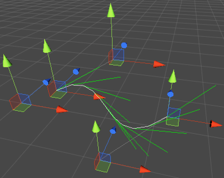
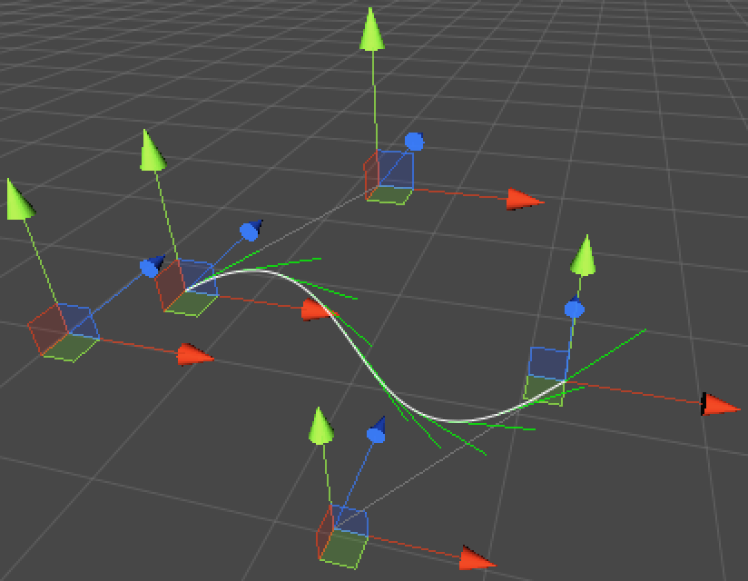
It is probably visually obvious by now that we draw our curve using straight line segments. We could increase the number of steps to improve the visual quality. We could also use an iterative approach to get accurate down to pixel level. But we can also use Unity’s Handles.DrawBezier method, which takes care of drawing nice cubic Beziér curves for us.
Let’s also show the directions in their own method and scale them to take up less space.
	private const float directionScale = 0.5f;

	private void OnSceneGUI () {
		curve = target as BezierCurve;
		handleTransform = curve.transform;
		handleRotation = Tools.pivotRotation == PivotRotation.Local ?
			handleTransform.rotation : Quaternion.identity;

		Vector3 p0 = ShowPoint(0);
		Vector3 p1 = ShowPoint(1);
		Vector3 p2 = ShowPoint(2);
		Vector3 p3 = ShowPoint(3);

		Handles.color = Color.gray;
		Handles.DrawLine(p0, p1);
		Handles.DrawLine(p2, p3);

		ShowDirections();
		Handles.DrawBezier(p0, p3, p1, p2, Color.white, null, 2f);
	}

	private void ShowDirections () {
		Handles.color = Color.green;
		Vector3 point = curve.GetPoint(0f);
		Handles.DrawLine(point, point + curve.GetDirection(0f) * directionScale);
		for (int i = 1; i <= lineSteps; i++) {
			point = curve.GetPoint(i / (float)lineSteps);
			Handles.DrawLine(point, point + curve.GetDirection(i / (float)lineSteps) * directionScale);
		}
	}
Splines
Having a single curve is nice, but to create complex paths we would need to concatenate multiple curves. Such a construct is known as a spline. Let’s create one by copying the BezierCurve code, changing the type to BezierSpline.
using UnityEngine;

public class BezierSpline : MonoBehaviour {

	public Vector3[] points;

	public Vector3 GetPoint (float t) {
		return transform.TransformPoint(Bezier.GetPoint(points[0], points[1], points[2], points[3], t));
	}

	public Vector3 GetVelocity (float t) {
		return transform.TransformPoint(
			Bezier.GetFirstDerivative(points[0], points[1], points[2], points[3], t)) - transform.position;
	}

	public Vector3 GetDirection (float t) {
		return GetVelocity(t).normalized;
	}

	public void Reset () {
		points = new Vector3[] {
			new Vector3(1f, 0f, 0f),
			new Vector3(2f, 0f, 0f),
			new Vector3(3f, 0f, 0f),
			new Vector3(4f, 0f, 0f)
		};
	}
}
We also create an editor for it, by copying and tweaking the code from BezierCurveInspector. We can then create a spline object and edit it, just like a curve.
using UnityEditor;
using UnityEngine;

[CustomEditor(typeof(BezierSpline))]
public class BezierSplineInspector : Editor {

	private const int lineSteps = 10;
	private const float directionScale = 0.5f;

	private BezierSpline spline;
	private Transform handleTransform;
	private Quaternion handleRotation;

	private void OnSceneGUI () {
		spline = target as BezierSpline;
		handleTransform = spline.transform;
		handleRotation = Tools.pivotRotation == PivotRotation.Local ?
			handleTransform.rotation : Quaternion.identity;

		Vector3 p0 = ShowPoint(0);
		Vector3 p1 = ShowPoint(1);
		Vector3 p2 = ShowPoint(2);
		Vector3 p3 = ShowPoint(3);

		Handles.color = Color.gray;
		Handles.DrawLine(p0, p1);
		Handles.DrawLine(p2, p3);

		ShowDirections();
		Handles.DrawBezier(p0, p3, p1, p2, Color.white, null, 2f);
	}

	private void ShowDirections () {
		Handles.color = Color.green;
		Vector3 point = spline.GetPoint(0f);
		Handles.DrawLine(point, point + spline.GetDirection(0f) * directionScale);
		for (int i = 1; i <= lineSteps; i++) {
			point = spline.GetPoint(i / (float)lineSteps);
			Handles.DrawLine(point, point + spline.GetDirection(i / (float)lineSteps) * directionScale);
		}
	}

	private Vector3 ShowPoint (int index) {
		Vector3 point = handleTransform.TransformPoint(spline.points[index]);
		EditorGUI.BeginChangeCheck();
		point = Handles.DoPositionHandle(point, handleRotation);
		if (EditorGUI.EndChangeCheck()) {
			Undo.RecordObject(spline, "Move Point");
			EditorUtility.SetDirty(spline);
			spline.points[index] = handleTransform.InverseTransformPoint(point);
		}
		return point;
	}
}
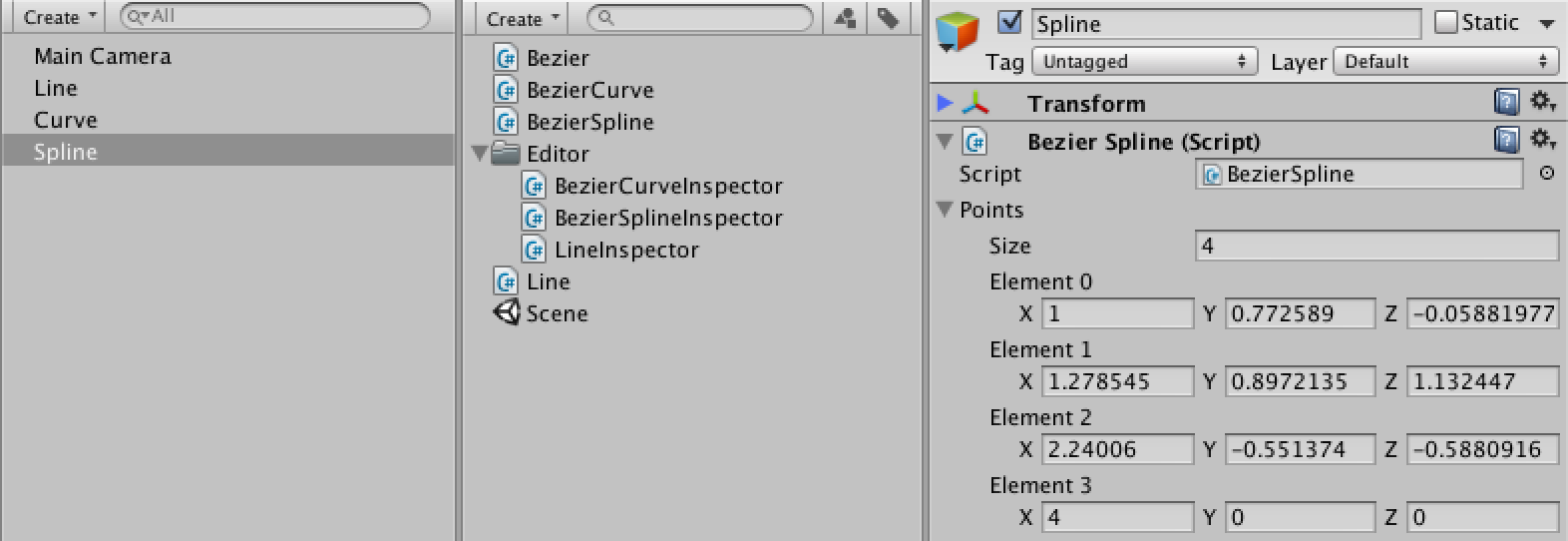
Let’s add a method to BezierSpline to add another curve to the spline. Because we want the spline to be continuous, the last point of the previous curve is the same as the first point of the next curve. So each extra curve adds three more points.
- What’s
ref? - How does
Array.Resizework?
	public void AddCurve () {
		Vector3 point = points[points.Length - 1];
		Array.Resize(ref points, points.Length + 3);
		point.x += 1f;
		points[points.Length - 3] = point;
		point.x += 1f;
		points[points.Length - 2] = point;
		point.x += 1f;
		points[points.Length - 1] = point;
	}
We’re using the Array.Resize method to create a larger array to hold the new points. It’s inside the System namespace, so we should declare that we’re using it at the top of our script.
using UnityEngine;
using System;
To actually be able to add a curve, we have to add a button to our spline’s inspector. We can customize the inspector that Unity uses for our component by overriding the OnInspectorGUI method of BezierSplineInspector. Note that this is not a special Unity method, it relies on inheritance.
To keep drawing the default inspector, we call the DrawDefaultInspector method. Then we use GUILayout to draw a button, which when clicked adds a curve.
- How does
GUILayout.Buttonwork? - Why assign
splinein both methods?
	public override void OnInspectorGUI () {
		DrawDefaultInspector();
		spline = target as BezierSpline;
		if (GUILayout.Button("Add Curve")) {
			Undo.RecordObject(spline, "Add Curve");
			spline.AddCurve();
			EditorUtility.SetDirty(spline);
		}
	}
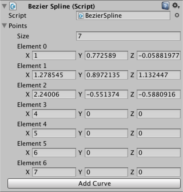
Of course we still only see the first curve. So we adjust BezierSplineInspector so it loops over all the curves.
	private void OnSceneGUI () {
		spline = target as BezierSpline;
		handleTransform = spline.transform;
		handleRotation = Tools.pivotRotation == PivotRotation.Local ?
			handleTransform.rotation : Quaternion.identity;

		Vector3 p0 = ShowPoint(0);
		for (int i = 1; i < spline.points.Length; i += 3) {
			Vector3 p1 = ShowPoint(i);
			Vector3 p2 = ShowPoint(i + 1);
			Vector3 p3 = ShowPoint(i + 2);

			Handles.color = Color.gray;
			Handles.DrawLine(p0, p1);
			Handles.DrawLine(p2, p3);

			Handles.DrawBezier(p0, p3, p1, p2, Color.white, null, 2f);
			p0 = p3;
		}
		ShowDirections();
	}
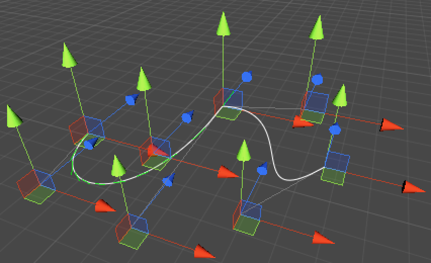
Now we can see all the curves, but the direction lines are only added to the first one. This is because BezierSpline‘s method also still only work with the first curve. It’s time to change that.
To cover the entire spline with a t going from zero to one, we first need to figure out which curve we’re on. We can get the curve’s index by multiplying t by the number of curves and then discarding the fraction. Let’s add a CurveCount property to make that easy.
	public int CurveCount {
		get {
			return (points.Length - 1) / 3;
		}
	}
After that we can reduce t to just the fractional part to get the interpolation value for our curve. To get to the actual points, we have to multiply the curve index by three.
However, this would fail when then original t equals one. In this case we can just set it to the last curve.
	public Vector3 GetPoint (float t) {
		int i;
		if (t >= 1f) {
			t = 1f;
			i = points.Length - 4;
		}
		else {
			t = Mathf.Clamp01(t) * CurveCount;
			i = (int)t;
			t -= i;
			i *= 3;
		}
		return transform.TransformPoint(Bezier.GetPoint(
			points[i], points[i + 1], points[i + 2], points[i + 3], t));
	}

	public Vector3 GetVelocity (float t) {
		int i;
		if (t >= 1f) {
			t = 1f;
			i = points.Length - 4;
		}
		else {
			t = Mathf.Clamp01(t) * CurveCount;
			i = (int)t;
			t -= i;
			i *= 3;
		}
		return transform.TransformPoint(Bezier.GetFirstDerivative(
			points[i], points[i + 1], points[i + 2], points[i + 3], t)) - transform.position;
	}
We now see direction lines across the entire spline, but we can improve the visualization by making sure that each curve segment gets the same amount of lines. Fortunately, it is easy to change BezierSplineInspector.ShowDirections so it uses BezierSpline.CurveCount to determine how many lines to draw.
	private const int stepsPerCurve = 10;

	private void ShowDirections () {
		Handles.color = Color.green;
		Vector3 point = spline.GetPoint(0f);
		Handles.DrawLine(point, point + spline.GetDirection(0f) * directionScale);
		int steps = stepsPerCurve * spline.CurveCount;
		for (int i = 1; i <= steps; i++) {
			point = spline.GetPoint(i / (float)steps);
			Handles.DrawLine(point, point + spline.GetDirection(i / (float)steps) * directionScale);
		}
	}
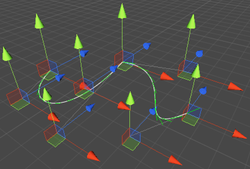
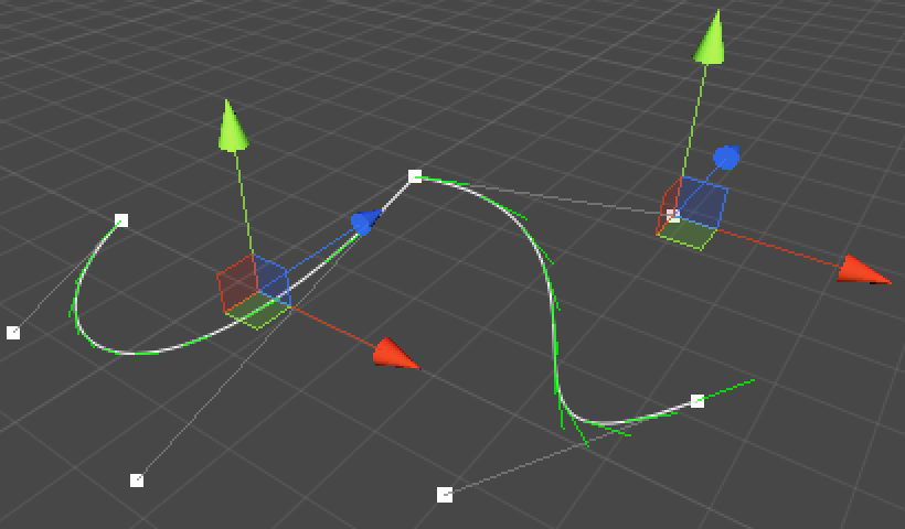
It’s rather crowded with all those transform handles. We could only show a handle for the active point. Then then other points can suffice with dots.
Let’s update ShowPoint so it shows a button instead of a position handle. This button will look like a white dot, which when clicked will turn into the active point. Then we only show the position handle if the point’s index matches the selected index, which we initialize at -1 so nothing is selected by default.
	private const float handleSize = 0.04f;
	private const float pickSize = 0.06f;

	private int selectedIndex = -1;

	private Vector3 ShowPoint (int index) {
		Vector3 point = handleTransform.TransformPoint(spline.points[index]);
		Handles.color = Color.white;
		if (Handles.Button(point, handleRotation, handleSize, pickSize, Handles.DotCap)) {
			selectedIndex = index;
		}
		if (selectedIndex == index) {
			EditorGUI.BeginChangeCheck();
			point = Handles.DoPositionHandle(point, handleRotation);
			if (EditorGUI.EndChangeCheck()) {
				Undo.RecordObject(spline, "Move Point");
				EditorUtility.SetDirty(spline);
				spline.points[index] = handleTransform.InverseTransformPoint(point);
			}
		}
		return point;
	}
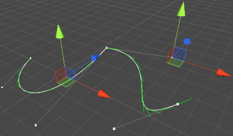
This works, but it is tough to get a good size for the dots. Depending on the scale you’re working at, they could end up either too large or too small. It would be nice if we could keep the screen size of the dots fixed, just like the position handles always have the same screen size. We can do this by factoring in HandleUtility.GetHandleSize. This method gives us a fixed screen size for any point in world space.
		float size = HandleUtility.GetHandleSize(point);
		Handles.color = Color.white;
		if (Handles.Button(point, handleRotation, size * handleSize, size * pickSize, Handles.DotCap)) {
			selectedIndex = index;
		}
Constraining Control Points
Although our spline is continuous, it sharply changes direction in between curve sections. These sudden changes in direction and speed are possible because the shared control point between two curves has two different velocities associated with it, one for each curve.
If we want the velocities to be equal, we must ensure that the two control points that define them – the third of the previous curve and the second of the next curve – mirror each other around the shared point. This ensures that the combined first and second derivatives are continuous.
Alternatively, we could align them but let their distance from the shared point differ. That will result in an abrubt change in velocity, while still keeping the direction continuous. In this case the combined first derivative is continuous, but the second is not.
The most flexible approach is to decide per curve boundary which contraints should apply, so we’ll do that. Of course, once we have these constraints we can’t just let anyone directly edit BezierSpline‘s points. So let’s make our array private and provide indirect access to it. Make sure to let Unity know that we still want to serialize our points, otherwise they won’t be saved.
	[SerializeField]
	private Vector3[] points;

	public int ControlPointCount {
		get {
			return points.Length;
		}
	}

	public Vector3 GetControlPoint (int index) {
		return points[index];
	}

	public void SetControlPoint (int index, Vector3 point) {
		points[index] = point;
	}
Now BezierSplineInspector must use the new methods and property instead of directly accessing the points array.
	private void OnSceneGUI () {
		spline = target as BezierSpline;
		handleTransform = spline.transform;
		handleRotation = Tools.pivotRotation == PivotRotation.Local ?
			handleTransform.rotation : Quaternion.identity;

		Vector3 p0 = ShowPoint(0);
		for (int i = 1; i < spline.ControlPointCount; i += 3) {
			Vector3 p1 = ShowPoint(i);
			Vector3 p2 = ShowPoint(i + 1);
			Vector3 p3 = ShowPoint(i + 2);

			Handles.color = Color.gray;
			Handles.DrawLine(p0, p1);
			Handles.DrawLine(p2, p3);

			Handles.DrawBezier(p0, p3, p1, p2, Color.white, null, 2f);
			p0 = p3;
		}
		ShowDirections();
	}

	private Vector3 ShowPoint (int index) {
		Vector3 point = handleTransform.TransformPoint(spline.GetControlPoint(index));
		float size = HandleUtility.GetHandleSize(point);
		Handles.color = Color.white;
		if (Handles.Button(point, handleRotation, size * handleSize, size * pickSize, Handles.DotCap)) {
			selectedIndex = index;
		}
		if (selectedIndex == index) {
			EditorGUI.BeginChangeCheck();
			point = Handles.DoPositionHandle(point, handleRotation);
			if (EditorGUI.EndChangeCheck()) {
				Undo.RecordObject(spline, "Move Point");
				EditorUtility.SetDirty(spline);
				spline.SetControlPoint(index, handleTransform.InverseTransformPoint(point));
			}
		}
		return point;
	}
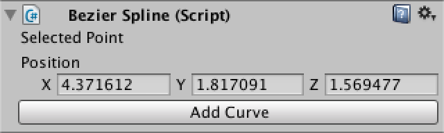
While we’re at it, we also no longer want to allow direct access to the array in the inspector, so remove the call to DrawDefaultInspector. To still allow changes via typing, let’s show a vector field for the selected point.
	public override void OnInspectorGUI () {
		spline = target as BezierSpline;
		if (selectedIndex >= 0 && selectedIndex < spline.ControlPointCount) {
			DrawSelectedPointInspector();
		}
		if (GUILayout.Button("Add Curve")) {
			Undo.RecordObject(spline, "Add Curve");
			spline.AddCurve();
			EditorUtility.SetDirty(spline);
		}
	}

	private void DrawSelectedPointInspector() {
		GUILayout.Label("Selected Point");
		EditorGUI.BeginChangeCheck();
		Vector3 point = EditorGUILayout.Vector3Field("Position", spline.GetControlPoint(selectedIndex));
		if (EditorGUI.EndChangeCheck()) {
			Undo.RecordObject(spline, "Move Point");
			EditorUtility.SetDirty(spline);
			spline.SetControlPoint(selectedIndex, point);
		}
	}
Unfortunately, it turns out that the inspector doesn’t refresh itself when we select a point in the scene view. We could fix this by calling SetDirty for the spline, but that’s not right because the spline didn’t change. Fortunately, we can issue a repaint request instead.
	private Vector3 ShowPoint (int index) {
		Vector3 point = handleTransform.TransformPoint(spline.GetControlPoint(index));
		float size = HandleUtility.GetHandleSize(point);
		Handles.color = Color.white;
		if (Handles.Button(point, handleRotation, size * handleSize, size * pickSize, Handles.DotCap)) {
			selectedIndex = index;
			Repaint();
		}
		if (selectedIndex == index) {
			EditorGUI.BeginChangeCheck();
			point = Handles.DoPositionHandle(point, handleRotation);
			if (EditorGUI.EndChangeCheck()) {
				Undo.RecordObject(spline, "Move Point");
				EditorUtility.SetDirty(spline);
				spline.SetControlPoint(index, handleTransform.InverseTransformPoint(point));
			}
		}
		return point;
	}
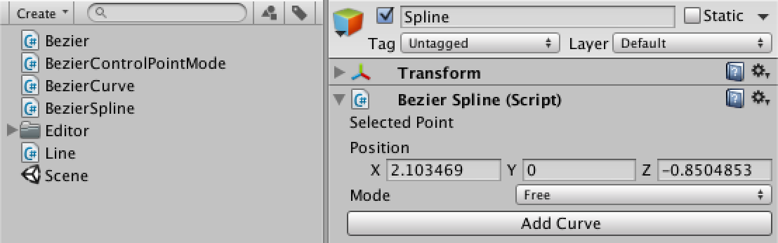
Let’s define an enumeration type to describe our three modes. Create a new script, remove the default code, and define an enum with the three options.
public enum BezierControlPointMode {
	Free,
	Aligned,
	Mirrored
}
Now we can add these modes to BezierSpline. We only need to store the mode in between curves, so let’s put them in an array with a length equal to the number of curves plus one. You’ll need to reset your spline or create a new one to make sure you have an array of the right size.
	[SerializeField]
	private BezierControlPointMode[] modes;

	public void AddCurve () {
		Vector3 point = points[points.Length - 1];
		Array.Resize(ref points, points.Length + 3);
		point.x += 1f;
		points[points.Length - 3] = point;
		point.x += 1f;
		points[points.Length - 2] = point;
		point.x += 1f;
		points[points.Length - 1] = point;

		Array.Resize(ref modes, modes.Length + 1);
		modes[modes.Length - 1] = modes[modes.Length - 2];
	}

	public void Reset () {
		points = new Vector3[] {
			new Vector3(1f, 0f, 0f),
			new Vector3(2f, 0f, 0f),
			new Vector3(3f, 0f, 0f),
			new Vector3(4f, 0f, 0f)
		};
		modes = new BezierControlPointMode[] {
			BezierControlPointMode.Free,
			BezierControlPointMode.Free
		};
	}
While we store the modes in between curves, it is convenient if we could get and set modes per control point. So we need to convert a point index into a mode index because in reality points share modes. As an example, the point index sequence 0, 1, 2, 3, 4, 5, 6 corresponds to the mode index sequence 0, 0, 1, 1, 1, 2, 2. So we need to add one and then divide by three.
	public BezierControlPointMode GetControlPointMode (int index) {
		return modes[(index + 1) / 3];
	}

	public void SetControlPointMode (int index, BezierControlPointMode mode) {
		modes[(index + 1) / 3] = mode;
	}
Now BezierSplineInspector can allow us to change the mode of the selected point. You will notice that changing the mode of one point also appears to change the mode of the points that are linked to it.
	private void DrawSelectedPointInspector() {
		GUILayout.Label("Selected Point");
		EditorGUI.BeginChangeCheck();
		Vector3 point = EditorGUILayout.Vector3Field("Position", spline.GetControlPoint(selectedIndex));
		if (EditorGUI.EndChangeCheck()) {
			Undo.RecordObject(spline, "Move Point");
			EditorUtility.SetDirty(spline);
			spline.SetControlPoint(selectedIndex, point);
		}
		EditorGUI.BeginChangeCheck();
		BezierControlPointMode mode = (BezierControlPointMode)
			EditorGUILayout.EnumPopup("Mode", spline.GetControlPointMode(selectedIndex));
		if (EditorGUI.EndChangeCheck()) {
			Undo.RecordObject(spline, "Change Point Mode");
			spline.SetControlPointMode(selectedIndex, mode);
			EditorUtility.SetDirty(spline);
		}
	}
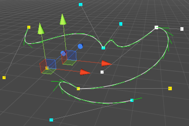
It would be useful if we also got some visual feedback about our node types in the scene view. We can easily add this by coloring the dots. I’ll use white for free, yellow for aligned, and cyan for mirrored.
	private static Color[] modeColors = {
		Color.white,
		Color.yellow,
		Color.cyan
	};

	private Vector3 ShowPoint (int index) {
		Vector3 point = handleTransform.TransformPoint(spline.GetControlPoint(index));
		float size = HandleUtility.GetHandleSize(point);
		Handles.color = modeColors[(int)spline.GetControlPointMode(index)];
		if (Handles.Button(point, handleRotation, size * handleSize, size * pickSize, Handles.DotCap)) {
			selectedIndex = index;
			Repaint();
		}
		if (selectedIndex == index) {
			EditorGUI.BeginChangeCheck();
			point = Handles.DoPositionHandle(point, handleRotation);
			if (EditorGUI.EndChangeCheck()) {
				Undo.RecordObject(spline, "Move Point");
				EditorUtility.SetDirty(spline);
				spline.SetControlPoint(index, handleTransform.InverseTransformPoint(point));
			}
		}
		return point;
	}
So far we’re just coloring points. It’s time to enforce the constraints. We add a new method to BezierSpline to do so and call it when a point is moved or a mode is changed. It takes a point index and begins by retrieving the relevant mode.
	public void SetControlPoint (int index, Vector3 point) {
		points[index] = point;
		EnforceMode(index);
	}

	public void SetControlPointMode (int index, BezierControlPointMode mode) {
		modes[(index + 1) / 3] = mode;
		EnforceMode(index);
	}

	private void EnforceMode (int index) {
		int modeIndex = (index + 1) / 3;
	}
We should check if we actually don’t have to enforce anything. This is the case when the mode is set to free, or when we’re at the end points of the curve. In these cases, we can return without doing anything.
	private void EnforceMode (int index) {
		int modeIndex = (index + 1) / 3;
		BezierControlPointMode mode = modes[modeIndex];
		if (mode == BezierControlPointMode.Free || modeIndex == 0 || modeIndex == modes.Length - 1) {
			return;
		}
	}
Now which point should we adjust? When we change a point’s mode, it is either a point in between curves or one of its neighbors. When we have the middle point selected, we can just keep the previous point fixed and enforce the constraints on the point on the opposite side. If we have one of the other points selected, we should keep that one fixed and adjust its opposite. That way our selected point always stays where it is. So let’s define the indices for these points.
		if (mode == BezierControlPointMode.Free || modeIndex == 0 || modeIndex == modes.Length - 1) {
			return;
		}

		int middleIndex = modeIndex * 3;
		int fixedIndex, enforcedIndex;
		if (index <= middleIndex) {
			fixedIndex = middleIndex - 1;
			enforcedIndex = middleIndex + 1;
		}
		else {
			fixedIndex = middleIndex + 1;
			enforcedIndex = middleIndex - 1;
		}
Let’s consider the mirrored case first. To mirror around the middle point, we have to take the vector from the middle to the fixed point – which is (fixed – middle) – and invert it. This is the enforced tangent, and adding it to the middle gives us our enforced point.
		if (index <= middleIndex) {
			fixedIndex = middleIndex - 1;
			enforcedIndex = middleIndex + 1;
		}
		else {
			fixedIndex = middleIndex + 1;
			enforcedIndex = middleIndex - 1;
		}

		Vector3 middle = points[middleIndex];
		Vector3 enforcedTangent = middle - points[fixedIndex];
		points[enforcedIndex] = middle + enforcedTangent;
For the aligned mode, we also have to make sure that the new tangent has the same length as the old one. So we normalize it and then multiply by the distance between the middle and the old enforced point.
		Vector3 enforcedTangent = middle - points[fixedIndex];
		if (mode == BezierControlPointMode.Aligned) {
			enforcedTangent = enforcedTangent.normalized * Vector3.Distance(middle, points[enforcedIndex]);
		}
		points[enforcedIndex] = middle + enforcedTangent;
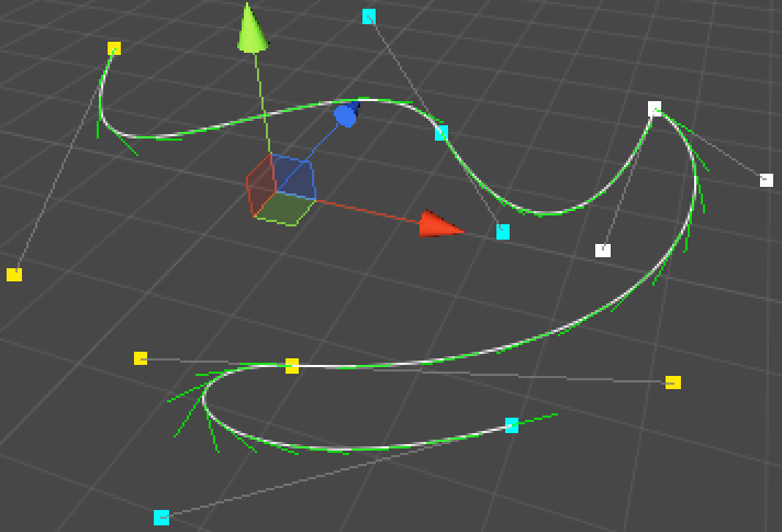
From now on, whenever you move a point or change a point’s mode, the constraints will be enforced. But when moving a middle point, the previous point always stays fixed and the next point is always enforced. This might be fine, but it’s intuitive if both other points move along with the middle one. So let’s adjust SetControlPoint so it moves them together.
	public void SetControlPoint (int index, Vector3 point) {
		if (index % 3 == 0) {
			Vector3 delta = point - points[index];
			if (index > 0) {
				points[index - 1] += delta;
			}
			if (index + 1 < points.Length) {
				points[index + 1] += delta;
			}
		}
		points[index] = point;
		EnforceMode(index);
	}
To wrap things up, we should also make sure that the constraints are enforced when we add a curve. We can do this by simply calling EnforceMode at the point where the new curve was added.
	public void AddCurve () {
		Vector3 point = points[points.Length - 1];
		Array.Resize(ref points, points.Length + 3);
		point.x += 1f;
		points[points.Length - 3] = point;
		point.x += 1f;
		points[points.Length - 2] = point;
		point.x += 1f;
		points[points.Length - 1] = point;

		Array.Resize(ref modes, modes.Length + 1);
		modes[modes.Length - 1] = modes[modes.Length - 2];
		EnforceMode(points.Length - 4);
	}
There is yet another constraint that we could add. By enforcing that the first and last control points share the same position, we can turn our spline into a loop. Of course, we also have to take modes into consideration as well.
So let’s add a loop property to BezierSpline. Whenever it is set to true, we make sure the modes of the end points match and we call SetPosition, trusting that it will take care of the position and mode constraints.
	[SerializeField]
	private bool loop;

	public bool Loop {
		get {
			return loop;
		}
		set {
			loop = value;
			if (value == true) {
				modes[modes.Length - 1] = modes[0];
				SetControlPoint(0, points[0]);
			}
		}
	}
Now we can add the loop property to BezierSplineInspector.
	public override void OnInspectorGUI () {
		spline = target as BezierSpline;
		EditorGUI.BeginChangeCheck();
		bool loop = EditorGUILayout.Toggle("Loop", spline.Loop);
		if (EditorGUI.EndChangeCheck()) {
			Undo.RecordObject(spline, "Toggle Loop");
			EditorUtility.SetDirty(spline);
			spline.Loop = loop;
		}
		if (selectedIndex >= 0 && selectedIndex < spline.ControlPointCount) {
			DrawSelectedPointInspector();
		}
		if (GUILayout.Button("Add Curve")) {
			Undo.RecordObject(spline, "Add Curve");
			spline.AddCurve();
			EditorUtility.SetDirty(spline);
		}
	}
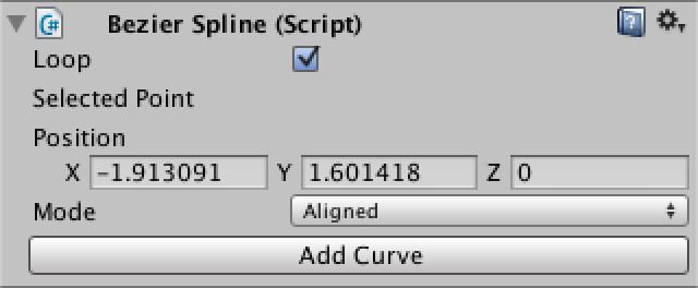
To correctly enforce the loop, we need to make a few more changes to BezierSpline.
First, SetControlPointMode needs to make sure that the first and last mode remain equal in case of a loop.
	public void SetControlPointMode (int index, BezierControlPointMode mode) {
		int modeIndex = (index + 1) / 3;
		modes[modeIndex] = mode;
		if (loop) {
			if (modeIndex == 0) {
				modes[modes.Length - 1] = mode;
			}
			else if (modeIndex == modes.Length - 1) {
				modes[0] = mode;
			}
		}
		EnforceMode(index);
	}
Next, SetControlPoint needs different edge cases when dealing with a loop, because it needs to wrap around the points array.
	public void SetControlPoint (int index, Vector3 point) {
		if (index % 3 == 0) {
			Vector3 delta = point - points[index];
			if (loop) {
				if (index == 0) {
					points[1] += delta;
					points[points.Length - 2] += delta;
					points[points.Length - 1] = point;
				}
				else if (index == points.Length - 1) {
					points[0] = point;
					points[1] += delta;
					points[index - 1] += delta;
				}
				else {
					points[index - 1] += delta;
					points[index + 1] += delta;
				}
			}
			else {
				if (index > 0) {
					points[index - 1] += delta;
				}
				if (index + 1 < points.Length) {
					points[index + 1] += delta;
				}
			}
		}
		points[index] = point;
		EnforceMode(index);
	}
Next, EnforceMode can now only bail at the end points when not looping. It also has to check whether the fixed or enforced point wraps around the array.
	private void EnforceMode (int index) {
		int modeIndex = (index + 1) / 3;
		BezierControlPointMode mode = modes[modeIndex];
		if (mode == BezierControlPointMode.Free || !loop && (modeIndex == 0 || modeIndex == modes.Length - 1)) {
			return;
		}

		int middleIndex = modeIndex * 3;
		int fixedIndex, enforcedIndex;
		if (index <= middleIndex) {
			fixedIndex = middleIndex - 1;
			if (fixedIndex < 0) {
				fixedIndex = points.Length - 2;
			}
			enforcedIndex = middleIndex + 1;
			if (enforcedIndex >= points.Length) {
				enforcedIndex = 1;
			}
		}
		else {
			fixedIndex = middleIndex + 1;
			if (fixedIndex >= points.Length) {
				fixedIndex = 1;
			}
			enforcedIndex = middleIndex - 1;
			if (enforcedIndex < 0) {
				enforcedIndex = points.Length - 2;
			}
		}

		Vector3 middle = points[middleIndex];
		Vector3 enforcedTangent = middle - points[fixedIndex];
		if (mode == BezierControlPointMode.Aligned) {
			enforcedTangent = enforcedTangent.normalized * Vector3.Distance(middle, points[enforcedIndex]);
		}
		points[enforcedIndex] = middle + enforcedTangent;
	}
And finally, we also have to take looping into account when adding a curve to the spline. The result might be a tangle, but it will remain a proper loop.
	public void AddCurve () {
		Vector3 point = points[points.Length - 1];
		Array.Resize(ref points, points.Length + 3);
		point.x += 1f;
		points[points.Length - 3] = point;
		point.x += 1f;
		points[points.Length - 2] = point;
		point.x += 1f;
		points[points.Length - 1] = point;

		Array.Resize(ref modes, modes.Length + 1);
		modes[modes.Length - 1] = modes[modes.Length - 2];
		EnforceMode(points.Length - 4);

		if (loop) {
			points[points.Length - 1] = points[0];
			modes[modes.Length - 1] = modes[0];
			EnforceMode(0);
		}
	}
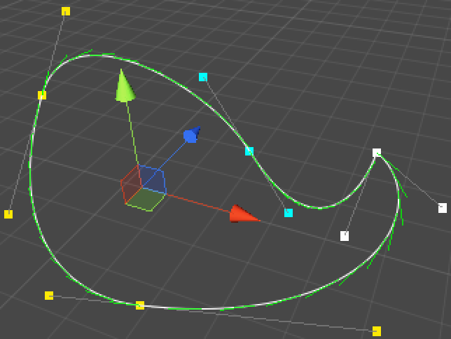
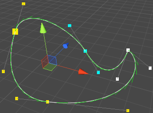
It is great that we have loops, but it is inconvenient that we can no longer see where the spline begins. We can make this obvious by letting BezierSplineInspector always double the size of the dot for the first point.
Note that in case of a loop the last point will be drawn on top of it, so if you clicked the middle of the big dot you’d select the last point, while if you clicked further from the center you’d get the first point.
	private Vector3 ShowPoint (int index) {
		Vector3 point = handleTransform.TransformPoint(spline.GetControlPoint(index));
		float size = HandleUtility.GetHandleSize(point);
		if (index == 0) {
			size *= 2f;
		}
		Handles.color = modeColors[(int)spline.GetControlPointMode(index)];
		if (Handles.Button(point, handleRotation, size * handleSize, size * pickSize, Handles.DotCap)) {
			selectedIndex = index;
			Repaint();
		}
		if (selectedIndex == index) {
			EditorGUI.BeginChangeCheck();
			point = Handles.DoPositionHandle(point, handleRotation);
			if (EditorGUI.EndChangeCheck()) {
				Undo.RecordObject(spline, "Move Point");
				EditorUtility.SetDirty(spline);
				spline.SetControlPoint(index, handleTransform.InverseTransformPoint(point));
			}
		}
		return point;
	}
Using Splines
We have been working with splines for a while now, but we haven’t used them for anything yet. There are uncountable things you can do with splines, for example moving an object alongs its path. Let’s create a SplineWalker component that does just that.
using UnityEngine;

public class SplineWalker : MonoBehaviour {

	public BezierSpline spline;

	public float duration;

	private float progress;

	private void Update () {
		progress += Time.deltaTime / duration;
		if (progress > 1f) {
			progress = 1f;
		}
		transform.localPosition = spline.GetPoint(progress);
	}
}
Now we can create a walker object, assign our spline, set a duration, and watch it move after we enter play mode. I simply used a cube and gave it smaller cubes to resemble eyes, so you can see in what direction it’s looking.
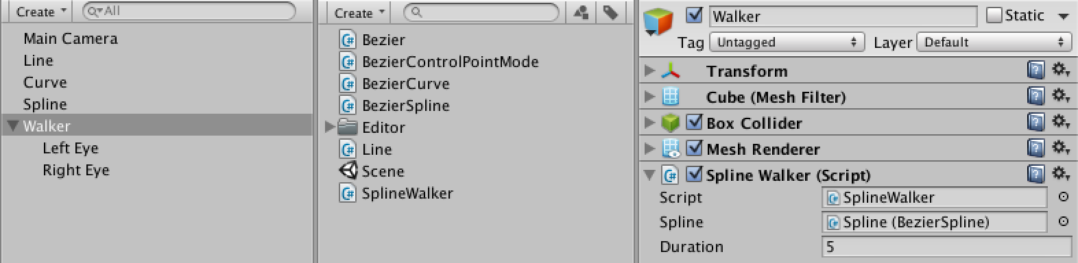
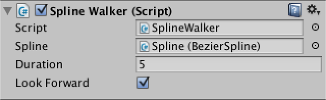
The walker now walks, but it’s not looking in the direction that it’s going. We can add an option for that.
	public bool lookForward;

	private void Update () {
		progress += Time.deltaTime / duration;
		if (progress > 1f) {
			progress = 1f;
		}
		Vector3 position = spline.GetPoint(progress);
		transform.localPosition = position;
		if (lookForward) {
			transform.LookAt(position + spline.GetDirection(progress));
		}
	}
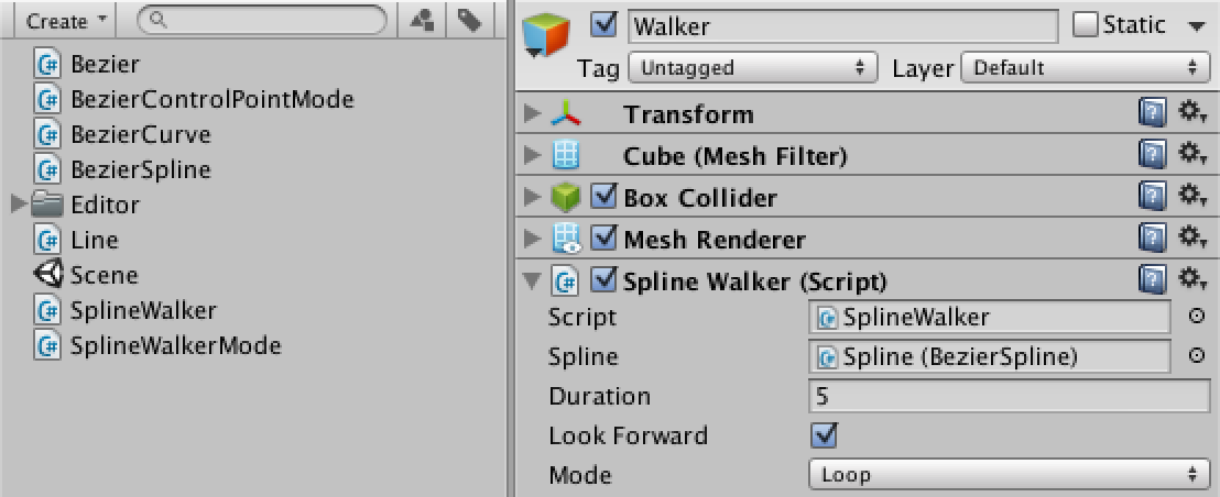
Another option is to keep looping the splines, instead of walking it just once. While we’re at it, we could also make the walker move back and forth, ping-ponging across the spline. Let’s create an enumeration to select between these modes.
public enum SplineWalkerMode {
	Once,
	Loop,
	PingPong
}
Now SplineWalker has to remember whether it’s going forward or backward. It also needs to adjust the progress when passing the spline ends depending on its mode.
	public SplineWalkerMode mode;

	private bool goingForward = true;

	private void Update () {
		if (goingForward) {
			progress += Time.deltaTime / duration;
			if (progress > 1f) {
				if (mode == SplineWalkerMode.Once) {
					progress = 1f;
				}
				else if (mode == SplineWalkerMode.Loop) {
					progress -= 1f;
				}
				else {
					progress = 2f - progress;
					goingForward = false;
				}
			}
		}
		else {
			progress -= Time.deltaTime / duration;
			if (progress < 0f) {
				progress = -progress;
				goingForward = true;
			}
		}

		Vector3 position = spline.GetPoint(progress);
		transform.localPosition = position;
		if (lookForward) {
			transform.LookAt(position + spline.GetDirection(progress));
		}
	}
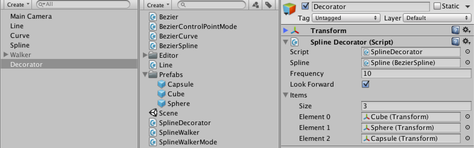
Another thing we could do is create a decorator that instantiates a sequence of items along a spline when it awakens. We also give it a forward-looking option, which applies to the items it spawns. Adding a frequency option to the item sequence allows for repetition. Of course, if either the frequency is zero or there are no items, we do nothing.
We need some items, so create a few prefabs for that purpose as well.
using UnityEngine;

public class SplineDecorator : MonoBehaviour {

	public BezierSpline spline;

	public int frequency;

	public bool lookForward;

	public Transform[] items;

	private void Awake () {
		if (frequency <= 0 || items == null || items.Length == 0) {
			return;
		}
		float stepSize = 1f / (frequency * items.Length);
		for (int p = 0, f = 0; f < frequency; f++) {
			for (int i = 0; i < items.Length; i++, p++) {
				Transform item = Instantiate(items[i]) as Transform;
				Vector3 position = spline.GetPoint(p * stepSize);
				item.transform.localPosition = position;
				if (lookForward) {
					item.transform.LookAt(position + spline.GetDirection(p * stepSize));
				}
				item.transform.parent = transform;
			}
		}
	}
}
This works well for loops, but it doesn’t go all the way to the end of splines that aren’t loops. We can fix this by increasing our step size to cover the entire length of the spline, as long as it’s not a loop and we have more than one item to place.
		if (frequency <= 0 || items == null || items.Length == 0) {
			return;
		}
		float stepSize = frequency * items.Length;
		if (spline.Loop || stepSize == 1) {
			stepSize = 1f / stepSize;
		}
		else {
			stepSize = 1f / (stepSize - 1);
		}
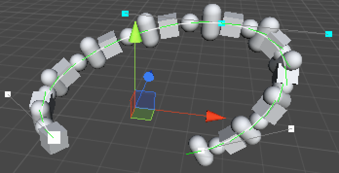
There are many more ways to use splines, and there’s also more features to add to the splines themselves. Like removing curves, or splitting a curve into two smaller ones, or merging two curves together. There are also other spline types to explore, like Centripetal Catmull-Rom or NURB. If you’re comfortable with Beziér, you should be able to handle those as well. So the tutorial ends here, enjoy walking your own path!
Enjoyed the tutorial? Help me make more by becoming a patron!
Downloads
curves-and-splines-01.unitypackageThe project after Lines.curves-and-splines-02.unitypackageThe project after Curves.curves-and-splines-03.unitypackageThe project after Splines.curves-and-splines-04.unitypackageThe project after Constraining Control Points.curves-and-splines-finished.unitypackageThe finished project.